Design Guidelines
Everything artists need to know before starting a project with us.
Table of Content
Overview of MX3D’s metal 3D printing technology (WAAM)
Robotic Wire Arc Additive Manufacturing (WAAM) is the core technology behind MX3D’s large-scale metal 3D printing. WAAM is an additive manufacturing process that uses robotic welding to deposit molten metal wire layer by layer, forming a three-dimensional object directly from a digital design.
This technique enables the creation of complex geometries in metal without the need for molds or traditional casting.

System Components: Control, Software & Materials
Robotic Motion & Toolpath Control
Our robotic arms follow a precisely generated toolpath derived from a 3D model. These toolpaths are created by converting your design into machine-readable instructions, taking into account parameters like deposition strategy, speed, and orientation.
MetalXL Software Platform
All printing operations are governed by MetalXL, our proprietary software suite, which coordinates toolpath planning, robot kinematics, and sensor feedback for quality assurance and safe execution.
Sensor-Driven Precision
Embedded sensors and process monitoring enable semi-autonomous operation, allowing for 24/7 manufacturing at a deposition rate of approximately 1–4 kg per hour, depending on material and geometry.
Compatible Metal Materials
The WAAM process uses standard welding wire. Any metal that can be welded—such as stainless steel, aluminum, or bronze—is potentially printable.
Design Input & Digital Preparation
Printing begins with a 3D digital file (CAD). However, you don’t need to bring one. You may start from a sketch, a clay maquette, or simply a concept — our team can work with you to translate your vision into a printable digital model.
Why WAAM is Ideal for Art Work?
- No molds or tooling required — ideal for complex, one-off, or experimental forms.
- Design freedom — unconstrained by traditional subtractive or casting limitations.
- Short lead times — large pieces can be printed within days.
- Material-efficient — WAAM enables topology optimization, reducing weight by 50% or more and minimizing material waste.
- Sustainable manufacturing — fewer production steps, less waste, and optimized use of material.
Design Scale & Printable Size
Object Scale
We specialize in medium to large-scale artworks and installations. Think life-size sculptures, architectural elements, or public space pieces — whether it’s a striking centerpiece or a functional art object.
For example, MX3D previously printed the world’s first 3D-printed steel bridge, installed in the heart of Amsterdam. The structure is over 12 meters long and demonstrates the potential of robotic metal printing at architectural scale.
Smaller-scale projects are equally welcome — from indoor sculptures to test prints or functional design pieces. If your idea exceeds our maximum print size, we can split it into printable sections and assembly afterwards.

Takenaka Connector
0.5m × 0.5m × 0.6m
MX3D Bridge
12 m × 4 m × 1.8 m


Completed work
Welding parts of the bench

Splitting & Assembly
For artworks larger than our robot’s build area, we can digitally split the model into printable sections.
These parts are designed for easy alignment and can be welded, bolted, or joined during assembly.
We’ll help plan the split so that seams are minimal and finishing remains smooth.
Test Prints
Want to try things out first? We offer small-scale test prints to preview textures, check geometry, or compare print settings (e.g., dot vs. fine).
Ideal for first-time users or refining surface expectations.
Sample part

 2")
Finished & installed work
Materials, Printing Strategies & Finishing Options
Commonly Used Materials
Stainless Steels
308LSi: EN ISO 14343 – A: 19.9LSi
316LSi: EN ISO 14343 – A: 19.12.3LSi
Duplex
ER2209 : EN ISO 14343 – A: 22.9.3NL
16.5.1: EN ISO 14343- A : 16 5 1
High-Strength Steels
NiMo: EN ISO 16834- A: G Mn3Ni1Mo
NiCrMo: EN ISO 16834-A G Mn3Ni1CrMo
NiCrMo: EN ISO 16834-A : G Mn4Ni2.5CrMo
Carbon Steels
G3Si-1 : EN ISO 14341-A: G 3Si1
G4Si-1 : EN ISO 14341-A: G 4Si1
G4M-o: EN ISO 14341-A : G 4Mo
EN ISO 14341-A : G Z2NiCu
EN ISO 17632-A : 1 H5
Bronze
CuSn6: EN ISO 24373: Cu 5180A (CuSn6P)
CuSi3 : ISO 24373 S Cu 6560 (CuSi3Mn1)
CuAl7: EN ISO 24373: S Cu 6100 (CuAl7)
CuAl8Ni6: EN ISO 24373 S Cu 6328 (CuAl9Ni5Fe3Mn2)
CuAl8Ni2: EN ISO 24373 : S Cu 6327 (CuAl8Ni2Fe2Mn2)
Corten Steel
ED-SG NiCu : eN ISO 14341-A G 42 2 M21 Z2NiCu
Aluminum
5356: EN ISO 18273: S Al 5356 (AlMg5Cr(A))
5183: EN ISO 18273: S Al 5183 (AlMg4,5Mn0,7(A))
4018: EN ISO 18273: S AI 4018 (AISi7Mg)
4046: EN ISO 18273: S AI 4046 (AISi10Mg)
5183: EN ISO 18273 : S Al 5183 (AlMg4.5Mn07(A))
5356: EN ISO 18273 : S Al 5356 (AlMg5Cr(A))
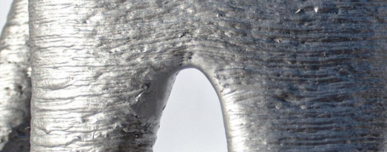
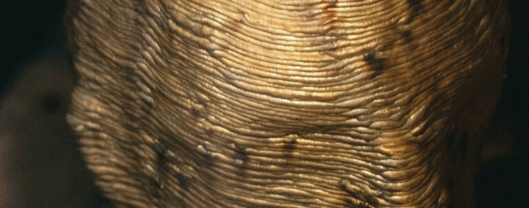
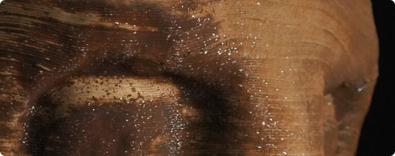
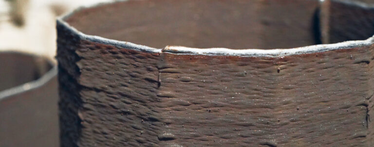
Print Techniques
Our robotic 3D printing supports multiple strategies, each producing distinct surface qualities and visual expressions. Whether you want a raw, expressive feel or a more delicate, refined texture, the choice of print style becomes part of your creative process.
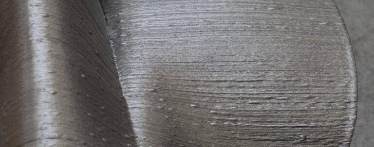
Fine Printing
Standard Printing

Dot Printing

Solid Printing
Post-Processing & Finishing Possibilities
Metal 3D printing always requires a level of manual or robotic post-processing steps. The post-processing step can be expanded to different surface finishes if a project requires a specific appearance.
MX3D has the capabilities to offer excellent quality post-processing services in-house or/and has a network of partners to outsource.


Geometry & Print Behavior
Understanding how the material is deposited helps inform better design decisions — from surface texture to production time.
Wall Thickness & Layer Build-up
- Typical wall thickness ranges from 3–9 mm, depending on the print mode and geometry. The effective structural thickness after printing is usually 2–8 mm.
- Layer height varies from 0.6–2.5 mm, depending on the selected printing strategy and wire type.
- To account for the ridged surface texture (with peaks of 0.5–1.0 mm), we recommend adding 1–2 mm extra to areas that require post-processing or precise dimensions.


Deposition Rates & Cooling
- Build speed depends on wire diameter, part shape, and number of parts printed in sequence.
- Complex prints may require intermediate cooling between layers, which slows down production but ensures better quality and stability.
- For large or intricate parts, plan with our team to optimize printing strategy and build sequence.
External Manipulator
Printing in a vertical upward direction, the maximum overhang a shape can have without requiring a rotation of the printing plate is around 40–45 degrees. In general, parts are printed vertically as much as possible.
For parts with an overhang of up to 45 degrees, we use a 6-axis robot. For parts with more complex angles, we use robots with an external manipulator. Depending on the geometry, this may result in different print line directions.

Overhangs, Holes & Print Orientation
Overhangs
- Surfaces angled over 45° without support may cause deformation
- Keep slopes gradual where possible

- 6-axis robot

- 6-axis robot

- 8-axis robot with different print direction

Holes & Voids
- Minimum supported hole diameter: 10–15 mm — smaller holes may close during printing.
- Horizontal holes and small features may deform or close during printing. To ensure accuracy, such holes are best oriented vertically or diagonally, or simply cut out after printing.
- For small features, consider orienting them vertically or diagonally to preserve shape.
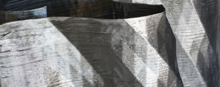
Orientation & Texture
Print orientation not only affects surface texture but also defines the visible direction of layer lines. The goal when orienting a part is to reduce overhangs, bridges and any other elements that may reduce print quality or success rate.
- Different parts of a single print may be built at different angles due to shape complexity or fabrication requirements. This can result in multi-directional layer lines across the same object.
- In general, vertical surfaces produce finer ridges, while angled or horizontal sections show more pronounced layering.

File Setup Guidelines
File Formats
We prefer native Rhino files (.3dm), STL, or STEP, but we can handle most file formats.
3D Scan Possibilities
We can provide 3D scanning services if you only have a physical object, converting it into a 3D file for further design or production.
Frequently Asked Questions
What is the estimated production time?
With 15+ in-house setups, we are able to achieve high efficiency in production. The exact timeline depends on factors such as design complexity, required surface quality, and chosen material. Our team will provide you with a tailored estimate based on your project.
How is the pricing calculated?
Pricing is influenced by several factors, including production speed, material choice, and design complexity. Because of this, costs are not always linear. Our experts carefully review each design file and provide a detailed, transparent, and fair quotation.
How far do you ship?
We provide international shipping to ensure our products reach you wherever you are. Please note that on-demand printing services are currently available exclusively at our Amsterdam headquarters.
I don’t know how to 3D model — can I still work with you?
Absolutely. You don’t need any technical skills to collaborate with us. We can start with a sketch, a mood board, or even just a conversation. Our team will help turn your idea into a 3D model that’s ready to print.
Can I create just one sculpture?
Yes! We specialize in custom, one-off pieces. Whether it’s a single artwork, a prototype, or a public installation, we’re happy to help you bring it to life—no mass production needed.
How can I design holes for the best printing results?
Small horizontal holes are prone to sagging or distortion during printing, especially if they fall below the recommended diameter of 10–15 mm. This often results in closed or deformed holes. To avoid this, we suggest enlarging the holes or orienting them vertically or diagonally. If needed, we can also cut or drill them after printing.
How can I achieve a smoother surface finish?
The surface texture of a print can vary depending on the selected printing strategy (e.g., Standard, Fine, or Dot Print) and the quality of the input model. Roughness may also come from a mesh that is too coarse or has issues like inverted normals. Choosing a finer print style and planning for post-processing (e.g., sanding or polishing) often helps.
Can I schedule a visit?
Absolutely! We welcome visitors to our headquarters in Amsterdam, where you can explore a wide range of samples and learn more about our process. Simply contact us to book an appointment. You can also experience our work in public installations worldwide, such as Dolium at Vrachelsplein, Oosterhout (NL), or The Underground Tree at Westerpark, Amsterdam (NL).
do you also print materials other than metal?
We only 3D print in metal. Our WAAM technology is specifically developed for large-scale, high-performance metal structures, which allows us to push the boundaries of design and engineering in ways that other materials cannot.
Let’s create together!
Curious if your idea can be printed in metal? Just ask. Whether you have a sketch, a full design, or just a dream, we’re here to help make it real.